...
With the Column Settings command, settings such as size, drawing, placement, material selection, structural material are accessed.
Location of the Column Settings Dialog
The column that appears after the column command is run is also available in the auxiliary toolbar.
...
In the Architectural Program
...
General Settings Tab
...
Specifications
...
You can access it under the ribbon menu Home tab Concrete title.
...
In Structural Program
You can access it under the ribbon menu Concrete tab Concrete title.
...
General Tab
...
Specifications |
|---|
Column ID  The column number is visible and can be changed. When the column is created, the name written here appears and the number increases by one in each new column. S01, S02, S03 etc. |
Group name  It is the line that allows to group the columns for transfer to the CSIKOL program. Columns grouped by giving the same group name can be transferred to the CSIKOL program at once by clicking Export/CSIKOL. |
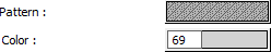
Pattern  |
It is the hatch type that applies to the colon. Clicking on hatch opens the Pattern Settings dialog. Select the hatch type from the look up table in this dialog. |
Color  It is the color of the column border lines. The selection is made on the color palette that is opened by clicking with the left mouse button and holding the button down. |
Circle column chord count  Circle column corner point is entered as an even number. The default is 40. The minimum value that can be entered is 10. |
Line |
type  The line type of the line forming the column in the plan is selected. Clicking the down arrow buttons to the right of the boxes opens the list of line types. From this list, the wanted line type is selected by clicking with the left mouse button. |
Width/Height:  |
The dimensions of the column are entered. While defining the column in the program, the first dimension is width, the second dimension is height. |
| title | Dahası |
|---|
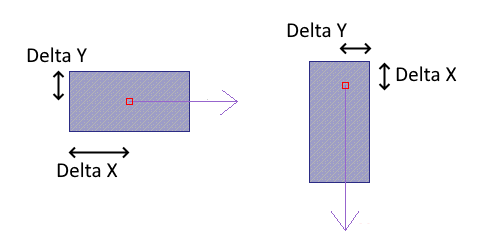
Delta X/Delta Y
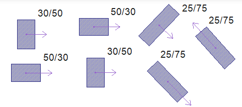
Columns can be found in any position (angle) in the plan. The program uses the column dimensions automatically regardless of the angle. When the "Draw column axis" option is selected in the Preferences dialog, arrows coming out of the joints of each column appear in the pane. These arrows indicate the x positive direction of the respective column itself. |
Delta X/Delta Y For rectangular columns, X and Y offset is entered. When a positive (+) value is entered for |
X offset, the column moves |
horizontally to the left. If a negative (-) value is entered, |
| Expand | ||
|---|---|---|
| ||
 |
Growth Limits
it shifts to the right. If a positive (+) value is entered for Y offset, the column moves vertically upwards, if a negative (-) value is entered, the column moves downwards. If the "Draw column axis" option is selected from Preferences tab, the column joint point is indicated by an arrow. The direction indicated by the arrow is the X axis. is the direction. Always look at the column with the arrow tip to the right. |
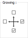
Growth limits If the column dimensions are changed in rectangular columns, the directions in which the column can grow and shrink are determined by these parameters. Columns can grow and shrink in the directions indicated by the ticked boxes. In addition, the marking here determines the growth direction of the column in the column application. |
| Expand | ||
|---|---|---|
| ||
|
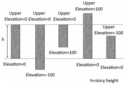
Upper elevation/Elevation
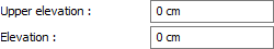
Upper elevation and Elevation parameters are used to shorten or extend the column from the top and bottom. As long as zero is left, column elevation general settings are taken as the floor height given in the diagram. In this case, the column bottom joint is on the floor floor and the upper node is on the floor ceiling.
| Expand | ||
|---|---|---|
| ||
 |
Shear

Determines the horizontal distance between the column top and bottom nodes. A value is entered here to define an inclined column.
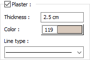
Plaster
If plaster will be drawn on the columns, it is marked. If this option is selected, plaster is drawn around the column as much as the value entered in the Plaster Thickness line. The color of the drawn plaster can be adjusted in the Plaster Color line. When other plaster assignable elements such as column walls are combined, plaster combinations are made automatically and excess lines at intersections are cleaned. Since plasters are architectural objects, column plasters are not drawn in Formwork Plan mode.
Plaster thickness, color, line type
Here, –X, + X, -Y and + Y directions should be considered locally with respect to the column. In the Preferences dialog, if the "Draw column axis" option is active, an arrow is drawn from the joint of the column in the plan. This arrow indicates the local + X direction of the corresponding column. Each time, look at the column with the arrowhead to the right. Growth limits should be determined according to these conditions. 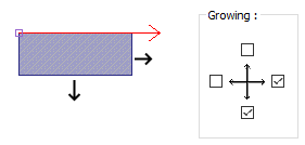 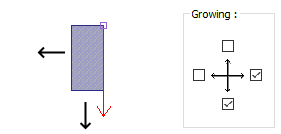 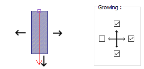 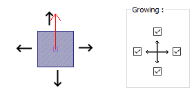 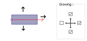 |
Upper elevation/Elevation Upper elevation and Elevation parameters are used to shorten or extend the column from the top and bottom. As long as zero is left, column elevation general settings are taken as the floor height given in the diagram. In this case, the column bottom joint is on the floor floor and the upper node is on the floor ceiling. If a positive value is entered in the upper elevation digit, the upper node of the column is extended up to the entered value, if a negative value is entered, the column becomes shorter. If a positive value is entered in the level section, the value entered at the lower end of the column becomes shorter from the bottom. In case of negative value the column gets longer to the bottom. |
Shear Determines the horizontal distance between the column top and bottom nodes. A value is entered here to define an inclined column. |
Plaster If plaster will be drawn on the columns, it is marked. If this option is selected, plaster is drawn around the column as much as the value entered in the Plaster Thickness line. The color of the drawn plaster can be adjusted in the Plaster Color line. When other plaster assignable elements such as column walls are combined, plaster combinations are made automatically and excess lines at intersections are cleaned. Since plasters are architectural objects, column plasters are not drawn in Formwork Plan mode. |
Plaster thickness, color, line type The plaster thickness to be drawn in the plan is entered. It is valid if the "Plaster" option is checked. If this option is not checked, no plaster is drawn on the columns. Column plasters are drawn only in Architectural Plan mode. Since plasters are architectural objects, column plasters are not drawn in Formwork Plan mode. The plaster color of the column is selected from the color palette that appears when you click. The line type of the line visible in the plan of the column plaster can be selected from the list. |
Polygon Column  Clicking this button, you can switch to the Polygon Column Settings dialog. In the Polygon Column Settings dialog, the parameters related to the polygon columns are set. Explanation is made in the Polygon Column Settings dialog. |
Material 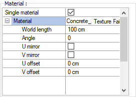 The material to be |
used on the |
face group surfaces of the |
column is selected |
from the list. Surfaces are covered with the selected material and displayed as such in |
Text Tab
...
Specifications
Description
ID X/ID Y
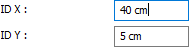
X and Y coordinates are entered according to the upper left corner of the column name text. Text If the X value is positive, the name text will move to the left, if it is negative, it will move to the right. Text scrolls up if the Y value is positive, and down if it is negative.
Dimension X/Dimension Y
renderings. Texture length is entered into the world length. For example; If 1 is entered, the selected material texture is taken as 1 meter and covered on the relevant walls. In the angle, the angle of the texture is entered. Touch the U and V offset. The motion value in the x and y plane is entered. With U and V mirroring, the texture is symmetrical with respect to the y and x planes. By selecting the single material option, the material selected in "Face group: 1" is used on all surfaces of the column. |
Text Tab
...
Specifications |
|---|
ID X/ID Y X and Y coordinates are entered according to the upper |
left corner of the column |
name text. Text If the |
X value is positive, the |
name text |
will move to the left, if it is negative, it |
will move to the right. |
Text scrolls up if the |
Y value is positive, |
and down if it is negative |
. |
ID placement
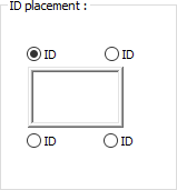
Determine the position where the column name will be written according to the figure in the dialog.
The program will place the name according to the position selected when the column was created.
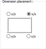
Dimension placement
Dimension X/Dimension Y X and Y coordinates are entered according to the upper right corner of the column size text. If the dimension X value is positive, the dimension text shifts to the left, if it is negative, it shifts to the right. If the dimension Y value is positive, the dimension text will scroll up, and if it is negative, it will scroll down. |
ID placement Determine the position where the column |
name will be written according to the figure in the dialog. The program will place the name according to the position selected when the column was created. |
Dimension placement Determine the position where the column size will be written relative to the column according to the figure in the dialog. The program will place the name according to the position selected when the column was created. |
ID and dimension combined  If checked, the column name and size are written together. If not checked, column name and column size are written in the places marked in the dialog. |
ID 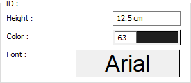 The height of the column name text is entered. The color box is selected from the color palette that is opened by clicking the left mouse button. If the text button just below is clicked, the Font Settings dialog opens. Column Name Text, font is set from this dialog. |
Dimension 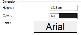 The height of the column size text is entered. The color box is selected from the color palette that is opened by clicking the left mouse button. If the button just below is clicked, the Font Settings dialog opens. Column Size Text, font type is set from this dialog. |
Structural/Concrete Tab
...
Specifications |
|---|
Structural material |

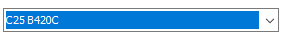 Select the static material to be used in the column element from the list. Static material can be defined as a reinforced concrete element under Materials in Building Tree. |
Defined section parameters |

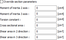 The section and geometric properties of the element are determined automatically and these are the values in accordance with the regulations. However, if you want to change the element section properties, mark this line and give the relevant values to the program. The program automatically calculates zero values and accepts non-zero entries as much as the entered value. |
2 axis moment of inertia The element is the minor moment of inertia. I = b 3 h / 12 3 axis moment of inertia The element is the major moment of inertia. I = bh 3 /12 50/25 For example, in a column three axis rectangular moment of inertia 50.50.50.25 / 12 = 260416 cm 4 is calculated as. Torsional moment of inertia It is the moment of inertia that defines the torsional stiffness of the element. Cross-sectional area It is the cross-sectional area value of the element. For example, in a 50/25 rectangular column, the cross section area of the element is 50.25 = 1250 cm 2 . Cutting area in 2 direction The element is the cutting area in the minor direction. Cutting area = 5/6. b. d For example, in a 50/25 rectangular column, 5 / 6.50.25 = 1041 cm2 Cutting area in 2 direction The element is the cutting area in the major direction. |
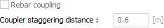
Rebar coupling  This |

This option can be selected if the column console is the support of a floor. Otherwise, it should not be marked.
Circular column stirrup type

option is activated if it is desired to make anchoring reinforcement attachment instead of lap joint in the columns. The confounding value is entered in the staggering distance box for the coupling application. |
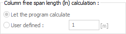
Column free span length (ln) calculation  The column free height is determined automatically according to the geometry of the elements. In some special cases, the desired clear opening value can be entered manually by using the defined option. |
Rebar splice 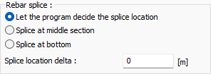 Rebar splice is found automatically with the let the program decide the splice location option. If desired, the rebar splice can be made in the middle section or bottom. The delta amount is entered for the splice location. |
Circular column stirrup type 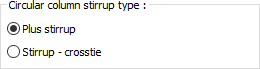 When the stirrup is selected, only stirrup design will be made in the circle column. When the stirrup - crosstie is chosen, it means that both stirrup design will be made in the circle column and the vertical reinforcements will be connected to each other with cryst. |
Bottom end embracement region length |
 The column free height is determined automatically according to the geometry of the elements. In
 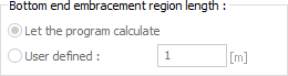 Column winding zones are found automatically according to the matters specified in the earthquake regulations. Stirrup tightening is made in the hugging areas. When the find a program option is selected, automatic adjustment is made to the regulation conditions. However, it may be desirable to arrange the length of the lower confinement zone at a different value, for example, for basements or columns to which high walls are connected. In this case, by entering the value in the Defined line, the lower end of the column can be formed in the desired length. If the length value gives the column length, the stirrup tightening is done in the column completely. |
Column free span length (ln) calculation
Lateral reinforcement leg counts 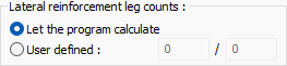 The number of lateral reinforcement legs is found automatically. In some special cases, the desired |
value can be entered manually in the box by using the defined option. |
Mason reinforcement attachment
Connection to foundation 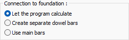 Foundation connections are found automatically. If desired, one of the options "Create separate dowel bars or use main bars" is selected. |
Sub basement level elevation 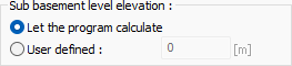 The sub-basement level elevation is found automatically. In some special cases, the desired sub basement level elevation can be entered manually in the box by using the user defined option. |
Multiple stirrup design |
 When the option is selected,
  If it is checked, it means that the program can design double stirrups in the column. Double stirrup design is determined automatically depending on the size of the column and the number of vertical reinforcements. In cases where a double stirrup design is not made in the column, a tie-break design is made according to the regulations. |
Always detail outside in the app

This column is a support for a cantilever slab  This option can be selected if the column console is the support of a floor. Otherwise, it should not be marked. |
Always detail outside in the app  When the option is selected, the column is not detailed on-site in the column application plan, instead the column is drawn as a scaled plan view. The detail expansion is also shown on the sheet edge. |
TBDY 2018 Tab
...
Specifications |
|---|
Description
Use response spectrum for vertical seismic effects  If it is marked, it is applied to the selected elements considering the vertical elastic acceleration spectrum according to the reference materials specified in Article 4.4.3.1 of TBDY 2018. These effects appear as a combination of Ez (R). When unchecked, the vertical earthquake effect is calculated from the formula Ez (G) = 2/3 * SDS * G according to the principles specified in Article 4.4.3.2 of TBDY and these effects appear as a combination of Ez (G). |
Thermal Parameters Tab
...
Specifications |
|---|
Override thermal parameters When checked, it activates T1 and T2 temperature loads on element basis. |
Temperature difference (T1)  The temperature difference of T1 loading is given. |
Temperature difference (T2)  The temperature difference of the T2 loading is given. |
Stiffness reduction factor  The stiffness reduction factor to be used in the temperature calculation for the relevant element is given. |
Stiffness Modifiers Tab
...
This tab is visible only when columns are selected and Object Properties and column settings are opened. In this tab, column stiffness can be reduced by a specific anchor value separately for earthquake, vertical, wind and soil thrust loads. Stiffness reduction can be applied optionally on the basis of element elasticity modulus or moment of inertia.
Specifications |
|---|
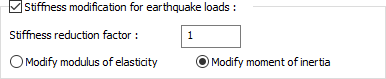 |
Column stiffness can be reduced by a specific anchor value separately for earthquake, vertical, wind and soil thrust loads. Stiffness reduction can be applied optionally on the basis of element elasticity modulus or moment of inertia. E = Reduction Factor * E or I = Reduction Factor * Applied as I. |
Performance Analysis Tab
...
Conforming transverse reinforcement

Specifications |
|---|
Description
Corrosion factor

It is a ratio used in building performance analysis. With the ratio written on this line, the wear occurring in the existing structures and reinforcements exposed to the corrosion conditions specified in the earthquake regulation can be taken into account in the performance calculation of the structure. The value defined in this row is multiplied with the existing reinforcement areas and the value found at the result of multiplication is considered as the reinforcement area. The mevcutal the yenial = multiplier *
Steel yield stress factor

It is used to reduce the steel yield stress of the elements. The value entered in this row is multiplied by the steel yield value of the element. yeniçelikakmadeğer * mevcutçelikakmadeğer of the multiplier =
Use fiber reinforced polymer 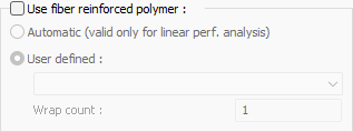 In columns that will be reinforced with fiber polymer, Fiber polymer properties are set by checking this option. Reinforcement is made by selecting one of the fiber polymers defined in the Fiber Reinforced Polymer Library and the count of wrap. |
Plastic hinge locations for pushover analysis 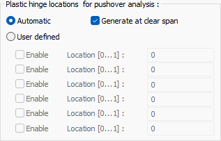 For pushover analysis, theplastic hinge can be identified automatically or manually. |
Corrosion factor  It is a ratio used in building performance analysis. With the ratio written on this line, the wear occurring in the existing structures and reinforcements exposed to the corrosion conditions specified in the earthquake regulation can be taken into account in the performance calculation of the structure. The value defined in this row is multiplied with the existing reinforcement areas and the value found at the result of multiplication is considered as the reinforcement area. |
Steel yield stress factor  It is used to reduce the steel yield stress of the elements. The value entered in this row is multiplied by the steel yield value of the element. |
Conforming transverse reinforcement 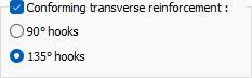 If there is stirrup tightening at the upper and lower ends of the column |
of the existing structure, this option is |
Apply 7.A.3 (Limitation oc axial forces)

selected. When this option is selected, it is assumed that the columns have confined concrete behavior. To define the hook angle of the stirrups in the tightening area of the existing column, one of the 90˚ or 135˚ hook options should be selected. |
Jacketing Tab
...
Specifications |
|---|
Jacketing material |

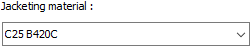 The static material belonging to the jacketing area is selected from the list. |
Thickness |

 The jacketing thickness of the column to be strengthened is entered. The program creates jacketing edges as many as the value entered here. |
Pattern and color |
 The color of the jacketing visible in the plan is determined here. You can select any of the hatches options by clicking the boxes with the mouse. |
Area to use |
for capacity check |
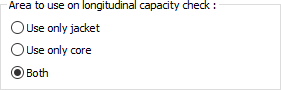
These are the options that determine which region will be taken into account as column area in axial load controls specified in earthquake regulations and TS500
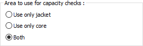 According to the earthquake regulations and material models specified in TS500, these are the options where the regions to be considered for calculating the sectional capacity to be used in existing structures are determined. 3 options are specified for the |
jacketing column. "Use only jacket", "Use only core", "Both". This control will be |
made automatically in the program for the area specified by the user. These options are not |
valid for uncoated columns. |
Steel diameter  The steel diameter of the jacket anchorage is determined. |
Vertical intervals  The vertical intervals distance of the jacket anchorages is determined. |
Anchorage length  The anchorage length of the jacket anchorages is determined. |
Major axis jacket connections 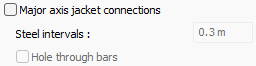 Major axis jacket connections and steel intervals are determined. Hole through bars can be added if desired. |
Minor axis jacket connections 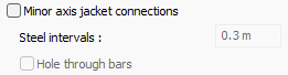 Minor axis jacket connections and steel intervals are determined. Hole through bars can be added if desired. |
Manual steel lengths  By checking the option, manual steel lengths are determined. |
Manual jacket-foundation connection lengths 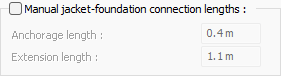 Manual jacket-foundation connection lengths are determined. Values are entered for the anchorage length and extension length. |
Punching Reinforcements Tab
...
Specifications |
|---|
Releases
Punching reinforcement type 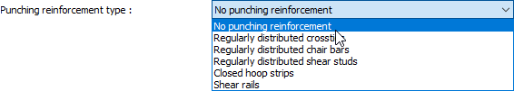 Punching reinforcement types described in Article 7.11.11 and Article 7.11.12 of TBDY 2018 can be selected from the list for the vertical bearing element being treated. If stapling reinforcement will not be used, "Without stapling equipment" |
type can be selected. You can edit the values given in the dialog according to the type selected. |
Always perform punching check at bottom end  If the option is checked, punching check is always performed at the bottom end. |
Always perform punching check at top end  If the option is checked, punching check is always performed at the top end. |
Components Tab
...
Add New Components: Assigns the projected building materials to the object for detailed building components metrics.
...
The parameters available in the component selection dialog are:
...
In the usage section;
No modification: The amount of material to be assigned for the object in question is marked when it is desired to be used in the size that was previously specified in the material definition.
...
The lines that appear in the Proportion list according to the column object and material size are as follows.
Column | ||
Measure | Listed | Explanation |
Constant | Independent | The fixed measure used will be used exactly as the amount. |
Length | Independent | It means that the length measure found while defining the material will be used exactly as the length value. |
Perimeter | It means that the length of the material will be found by multiplying the length measurement found while defining the material and the perimeter of the column. | |
Height | It means that the length of the material will be found by multiplying the length of the column with the height of the column. | |
Area | Independent | The area measure found when defining the material will be used exactly as the area of the material. |
Side area | It means that the area measure found while defining the material will be used by multiplying it by the sum of the side areas of the column. | |
Crosssection area | It means that the area measure found while defining the material will be multiplied by the cross section of the column. | |
Volume | Independent | It means that the volume measure found when defining the material will be used exactly as the volume of the material. |
Volume | It means that the volume measurement found when defining the material will be used by multiplying the column volume. | |
Count | Independent | The number measure found while defining the material will be used exactly as the material number. |
Count | Number measure, number of materials found when defining the material | |
...
Next Topic